You've purchased a Td-Free PCB!
Purchased (not received!) your Td-Free PCB before 1st May 2025? Click here!
Congrats on that! Let's start building a Td-Free from your PCB!
Get Started
Print your case
Start by printing the case that you can download over at Printables! Make sure you're printing the "Filament Path" with a black filament.
Overview
1. Part Overview
Let's start by getting an overview of all the parts we need for the assembly!
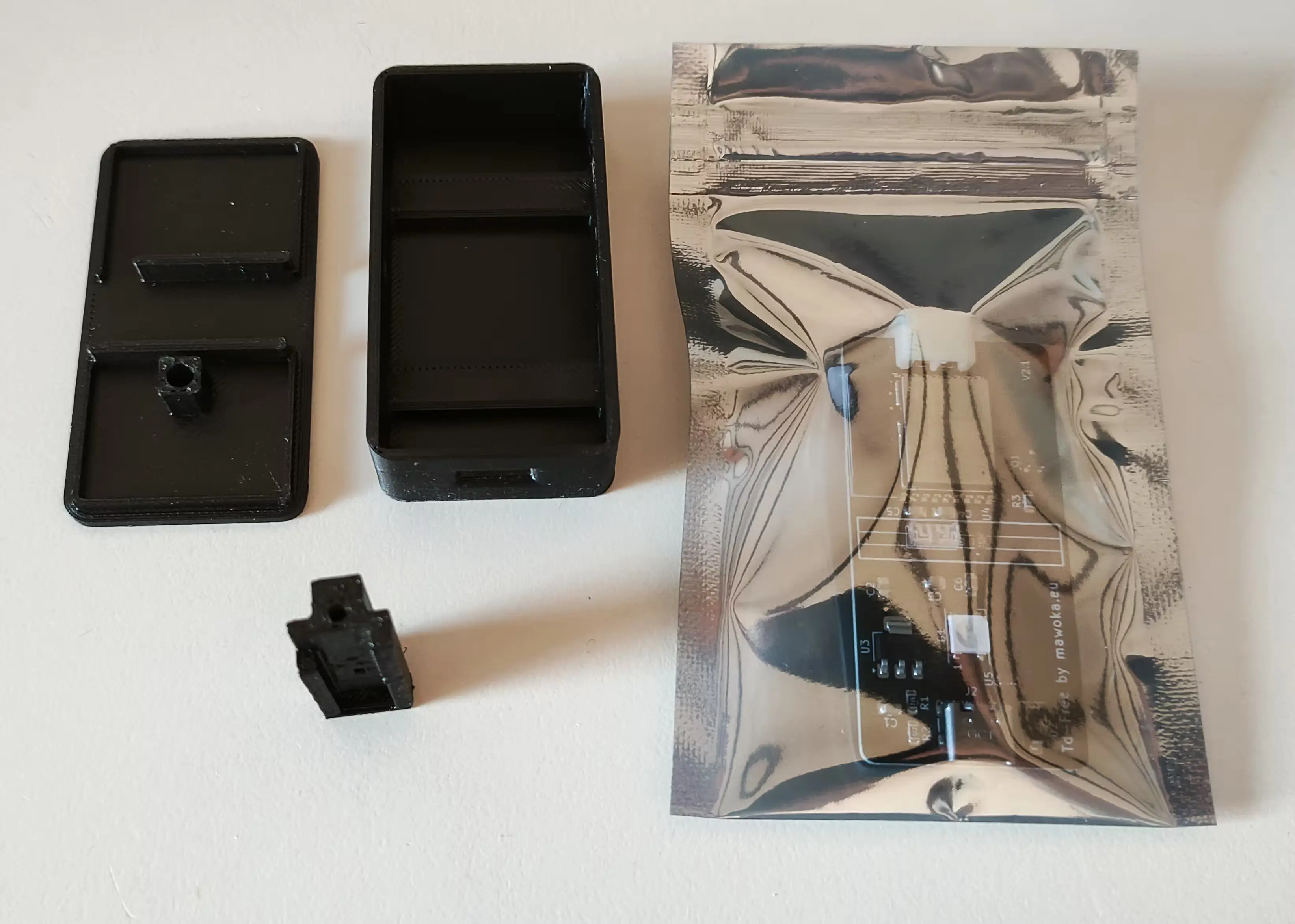
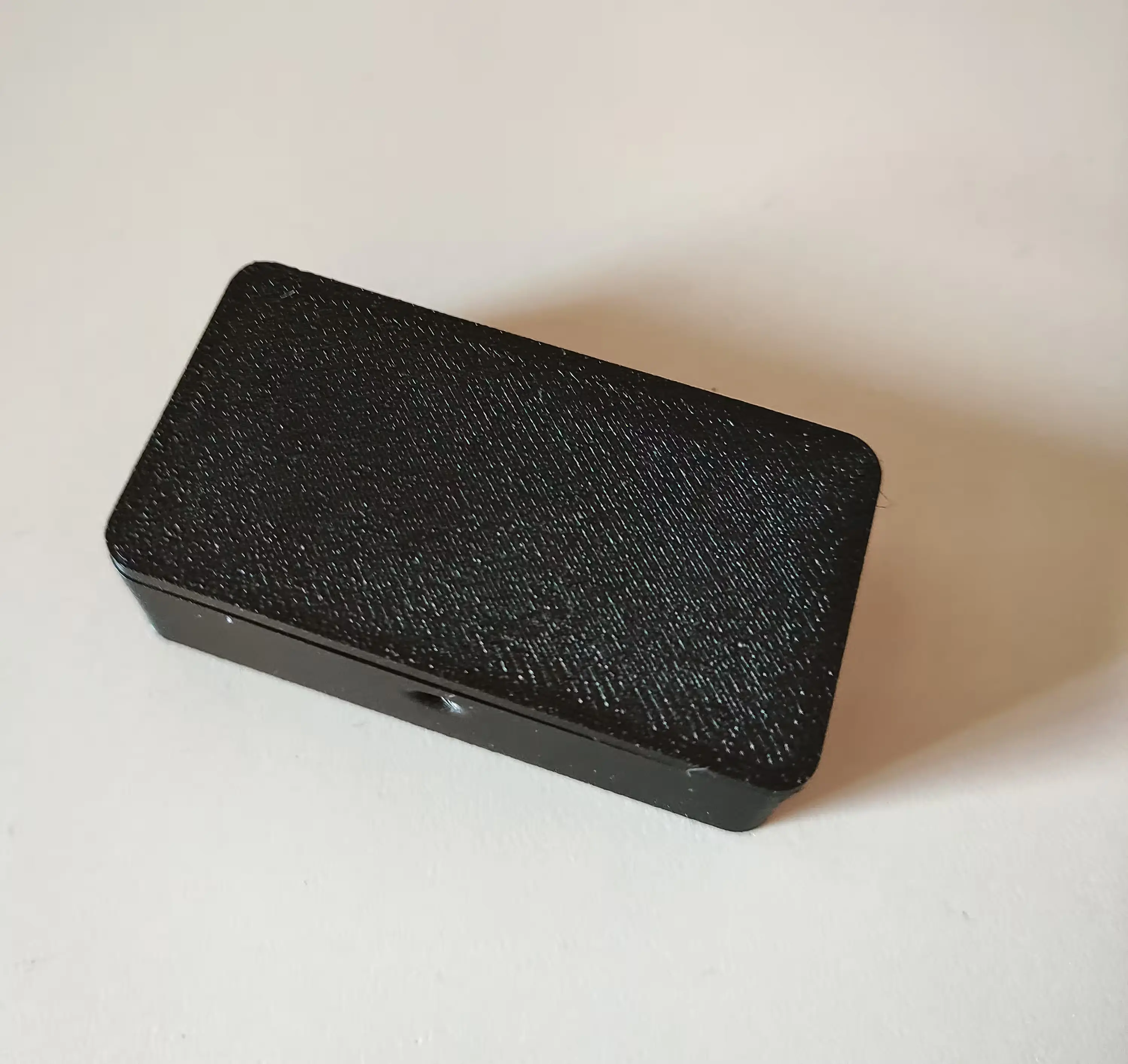
The small black part is the so-called "Filament Path", just so you know as I'll be using this term from now on.
Tip: You can click on any image to view it in fullscreen!
2. Unpack the PCB
As you might have guessed, the PCB needs to be unpacked, so get it out of the bag. You don't need to cut it, it can just be opened and reused.
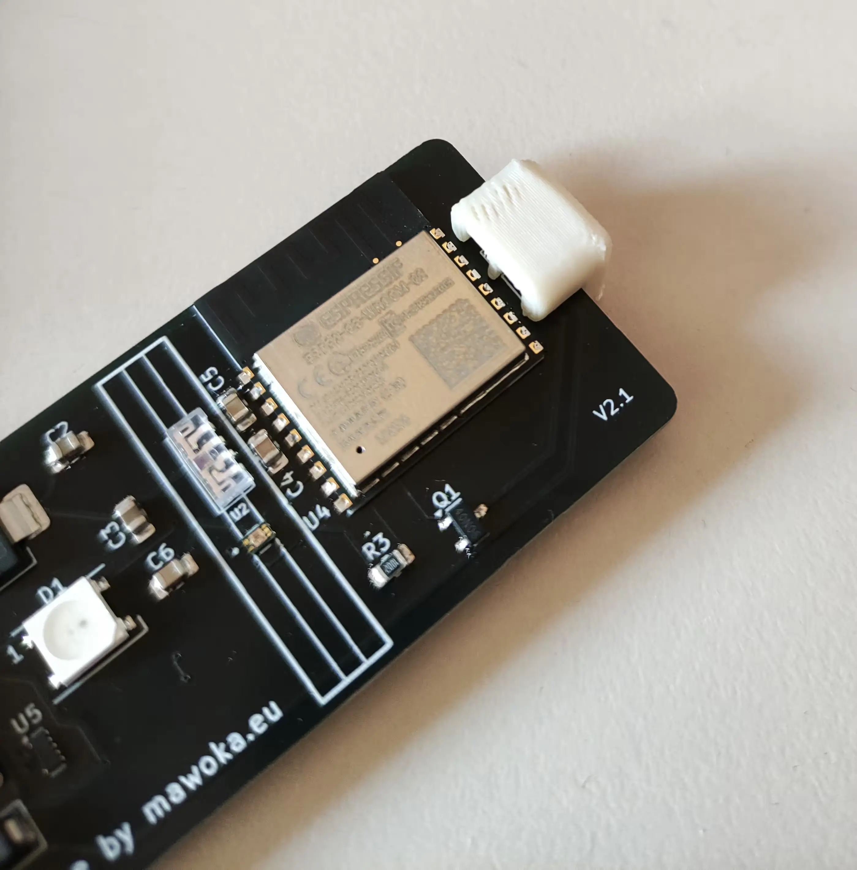
The white/beige part has to be removed as well. It protects the cables from breaking during shipping. Slide it carefully into the top-righthand corner of the photo. You can safely dispose of it on your compost. And no, this isn't a joke! It's made from PHA, a plastic that can be composted in your garden. For real! It also doesn't leave any microplastics behind. And this is PHA and thus truly compostable, not like PLA where it's only theoretically compostable (in an industrial environment).
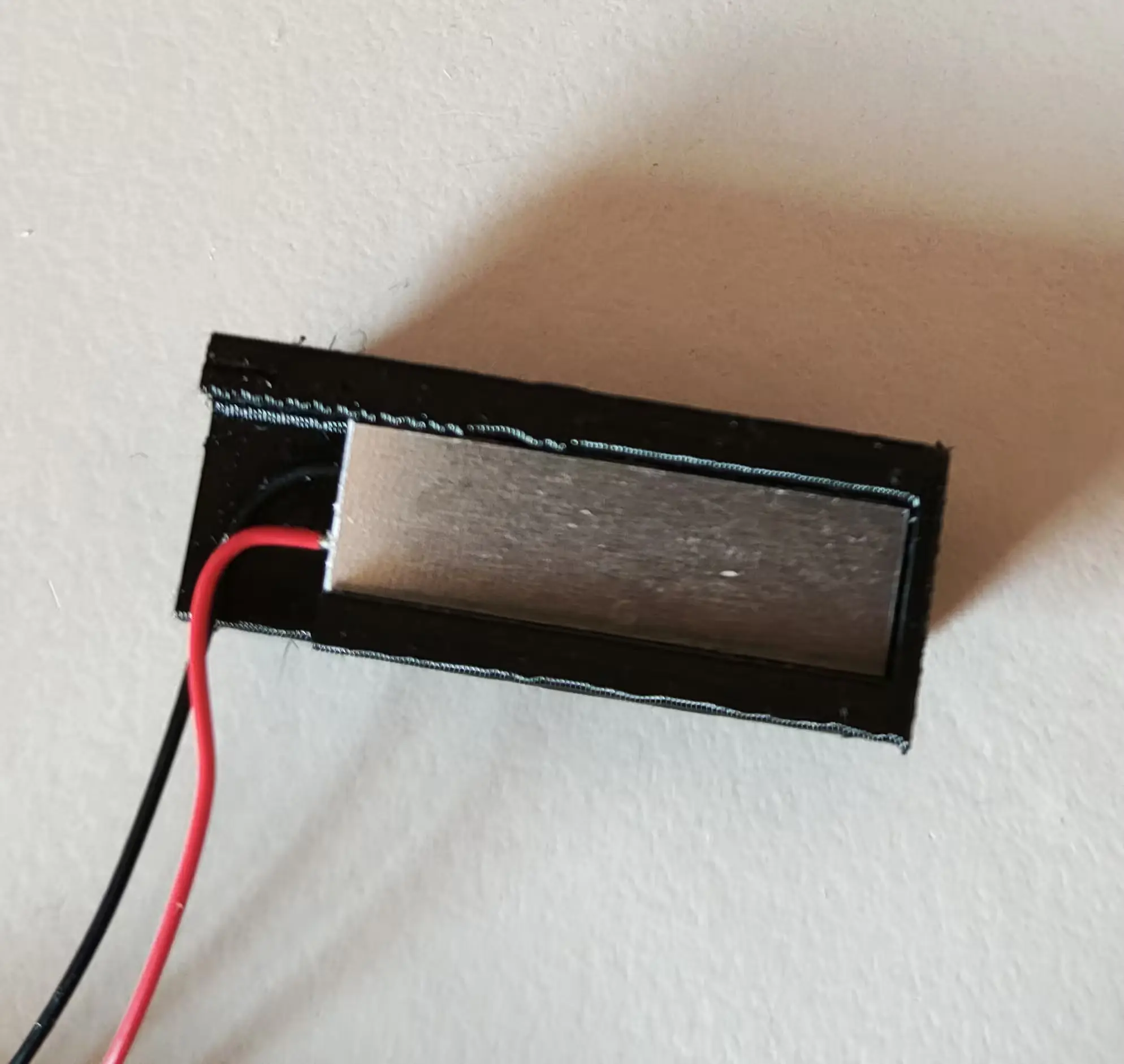
3. Insert the LED into the Filament Path
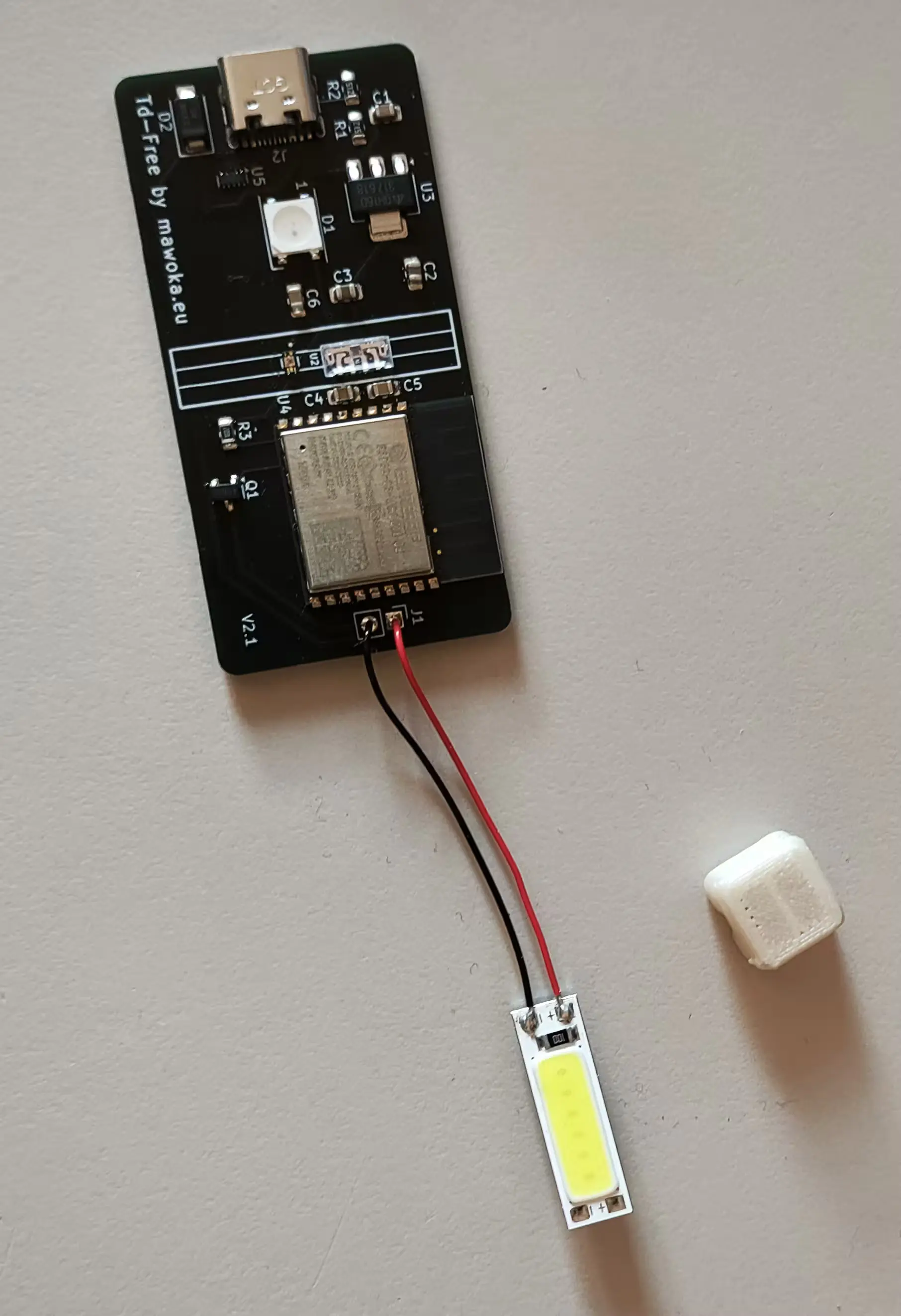
Next step is to insert/press the LED into the Filament Path.
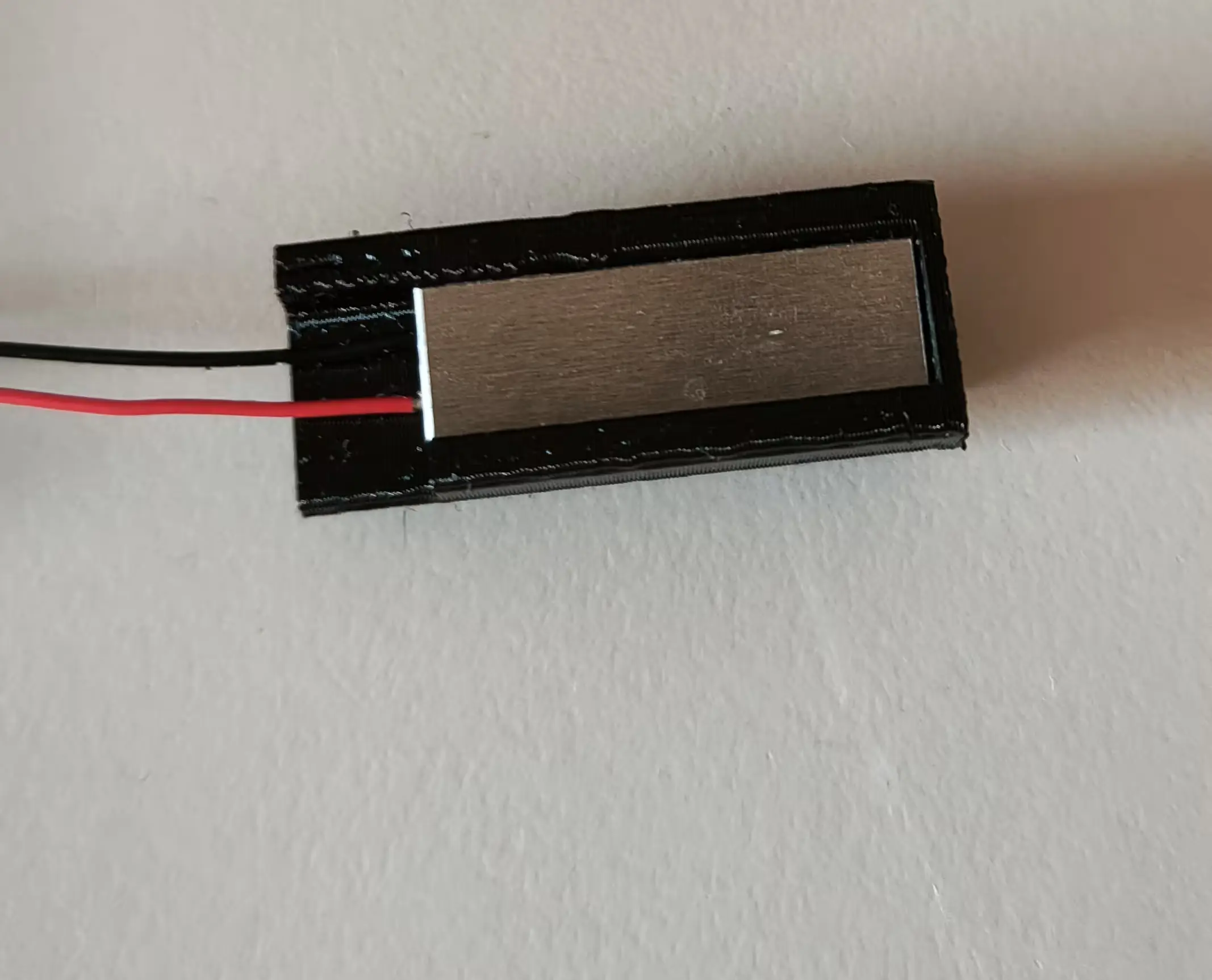
Here it's important that the LED is as far in as possible so there's as much distance between the cables and the free side. Don't press it in too hard, it only has to hold. If it sits at a slight angle, it doesn't matter.
You'll have to bend the cables so they don't interfere with the case later on. When bending, make sure to not break the cables off.
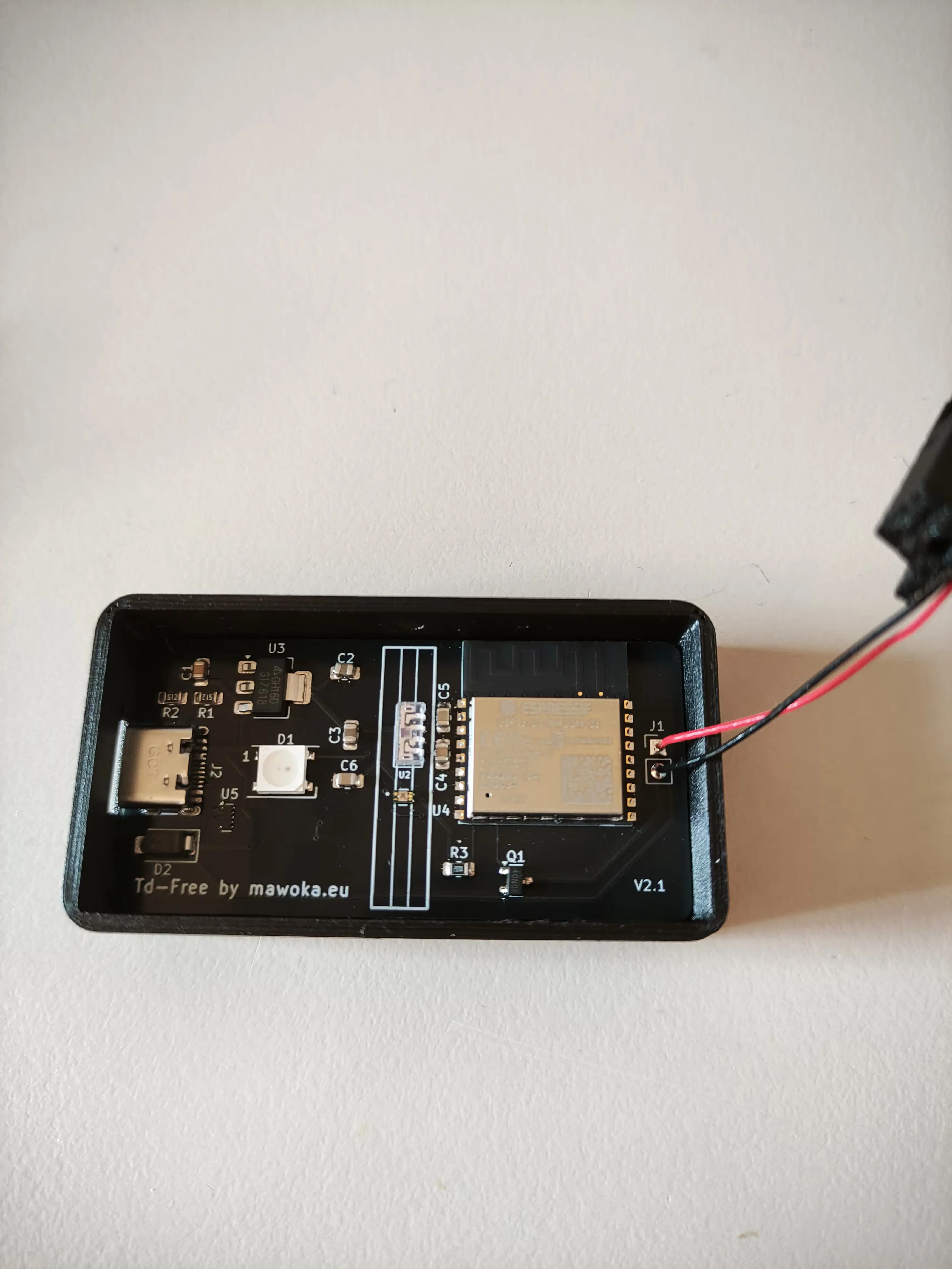
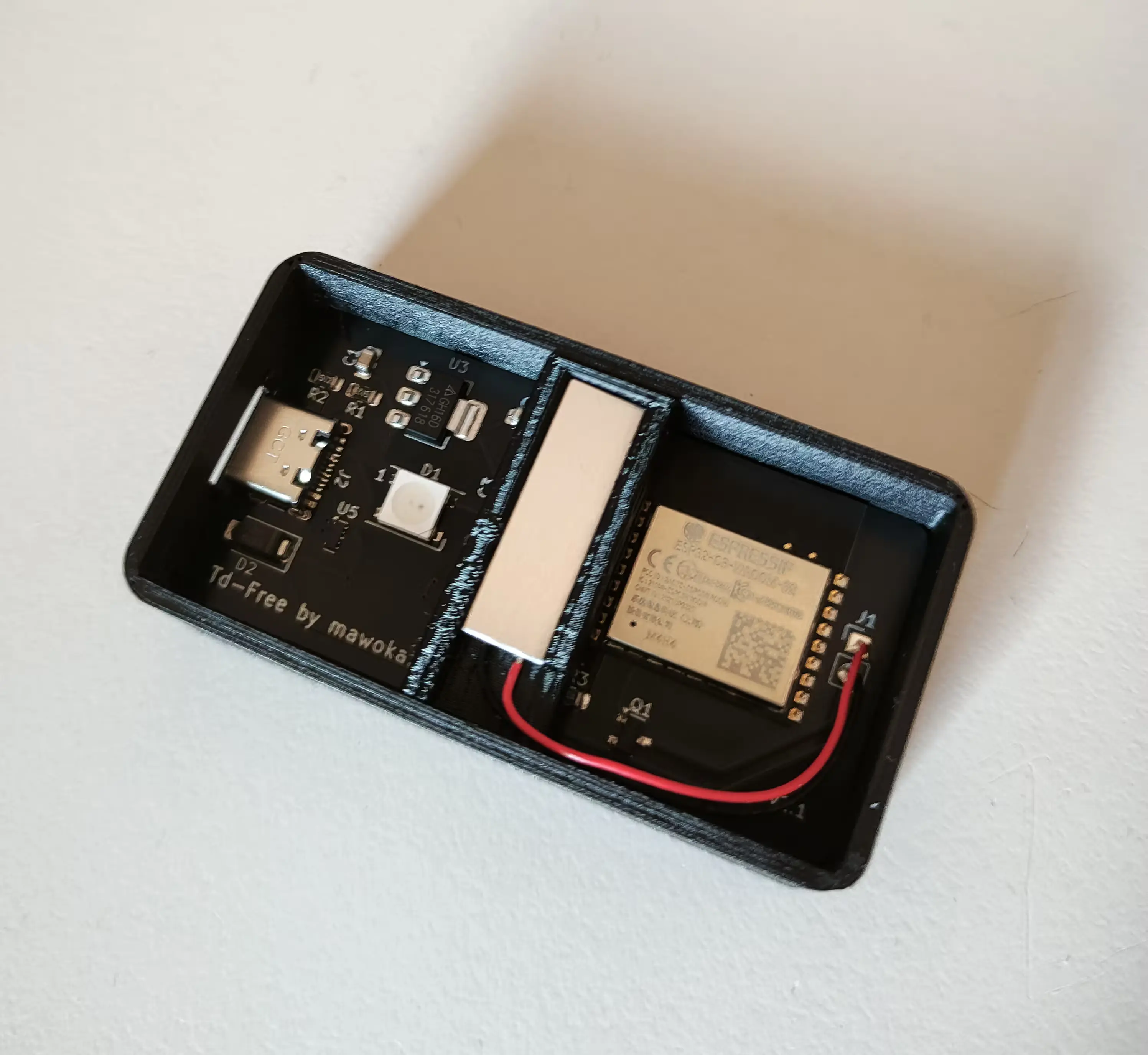
4. Put the PCB into the case
That should be super easy: Just drop the PCB in, it should fall into place on its own.
5. Placing the Filament Path
Okay, so this is gonna be a bit tricky, so buckle up! Actually, it's not too difficult, you'll just have to be careful not to rip the sensors off the board. For that, carefully align the Filament Path as shown in the pictures below.
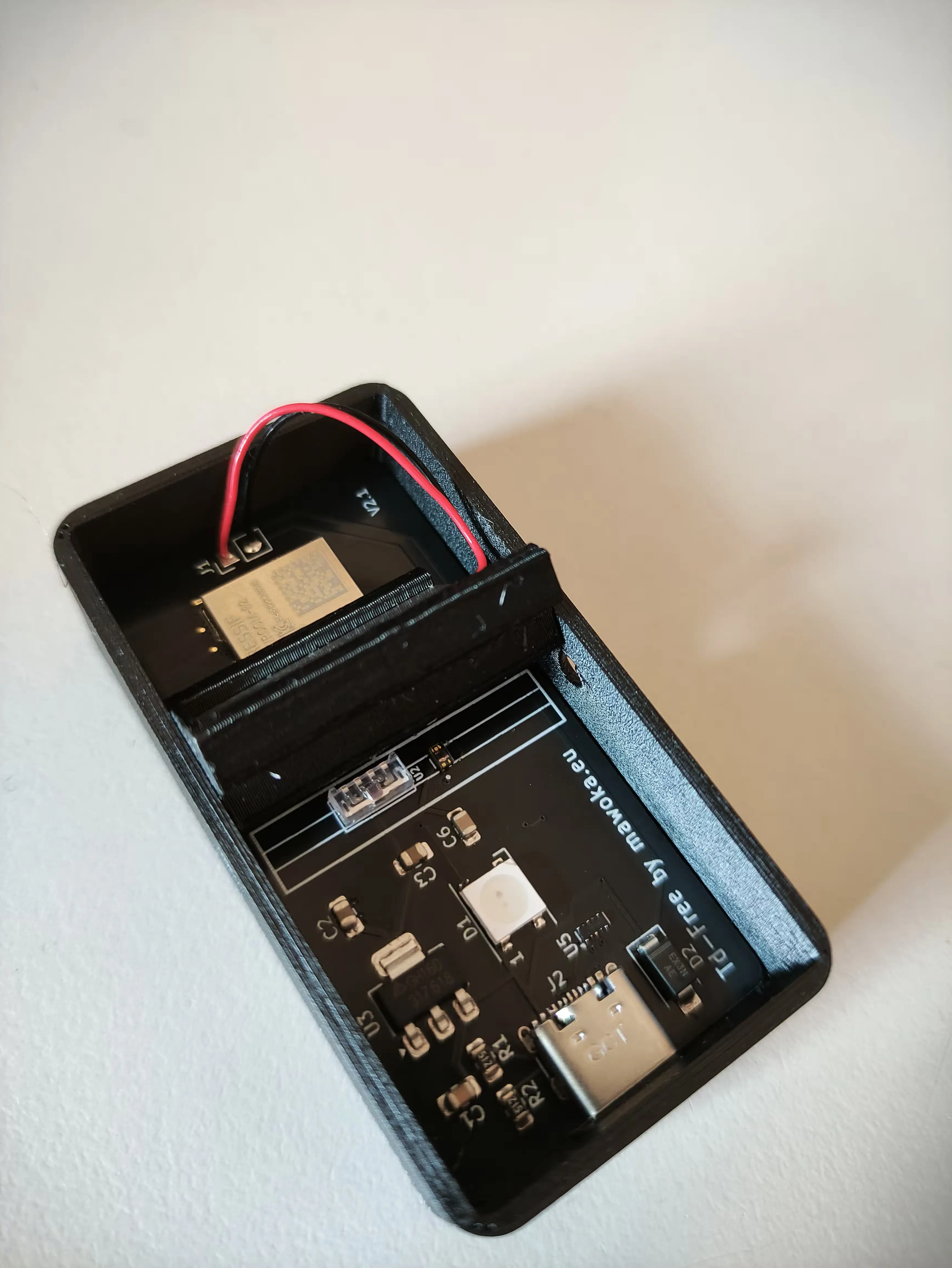
If it's properly aligned with the white drawings on the PCB, you can carefully fold it down.
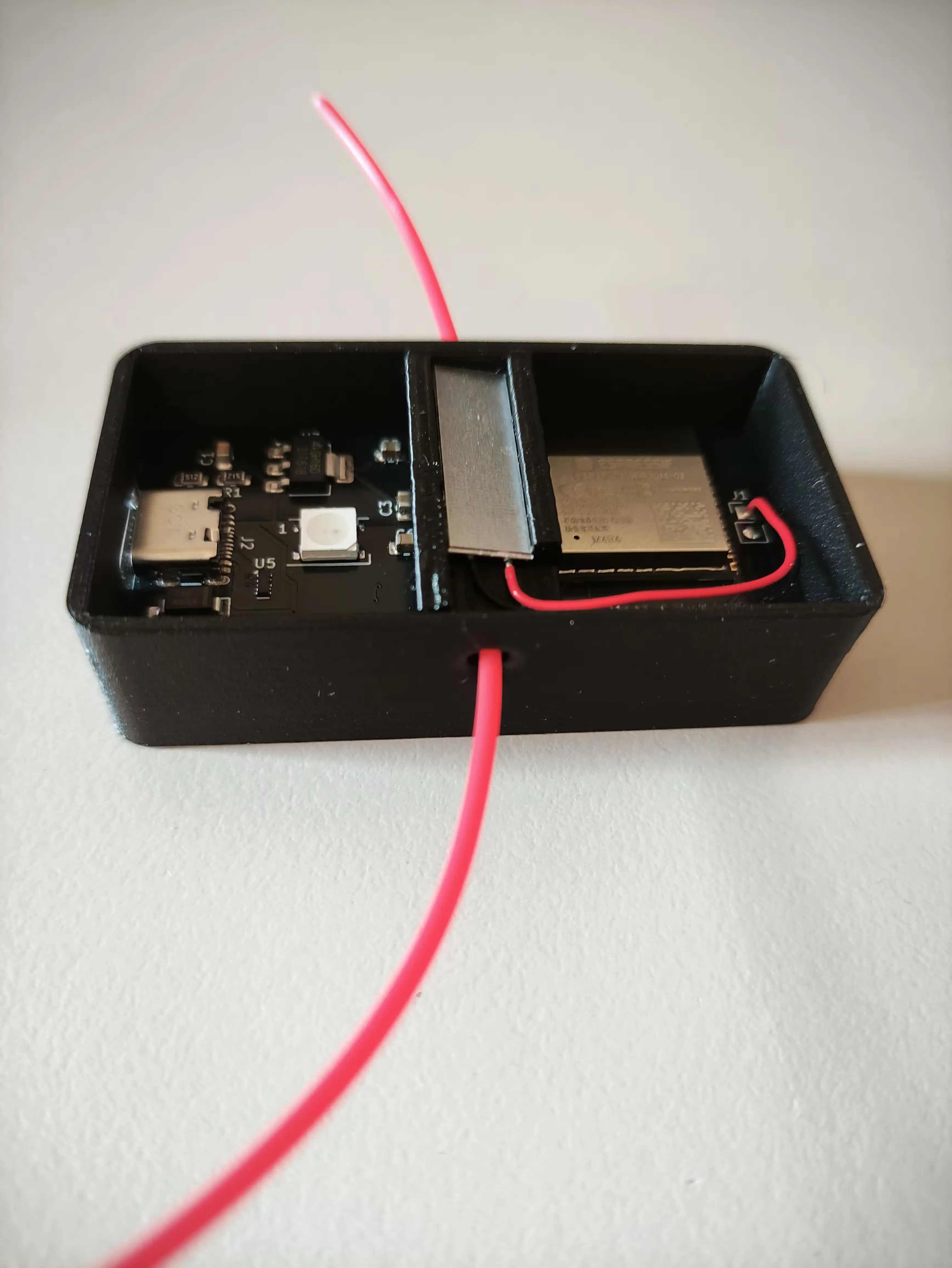
If you've done everything correctly, you should be able to move some filament through the Td-Free. If that doesn't work, the Filament Path is either misaligned or there is a print defect inside of the Filament Path.
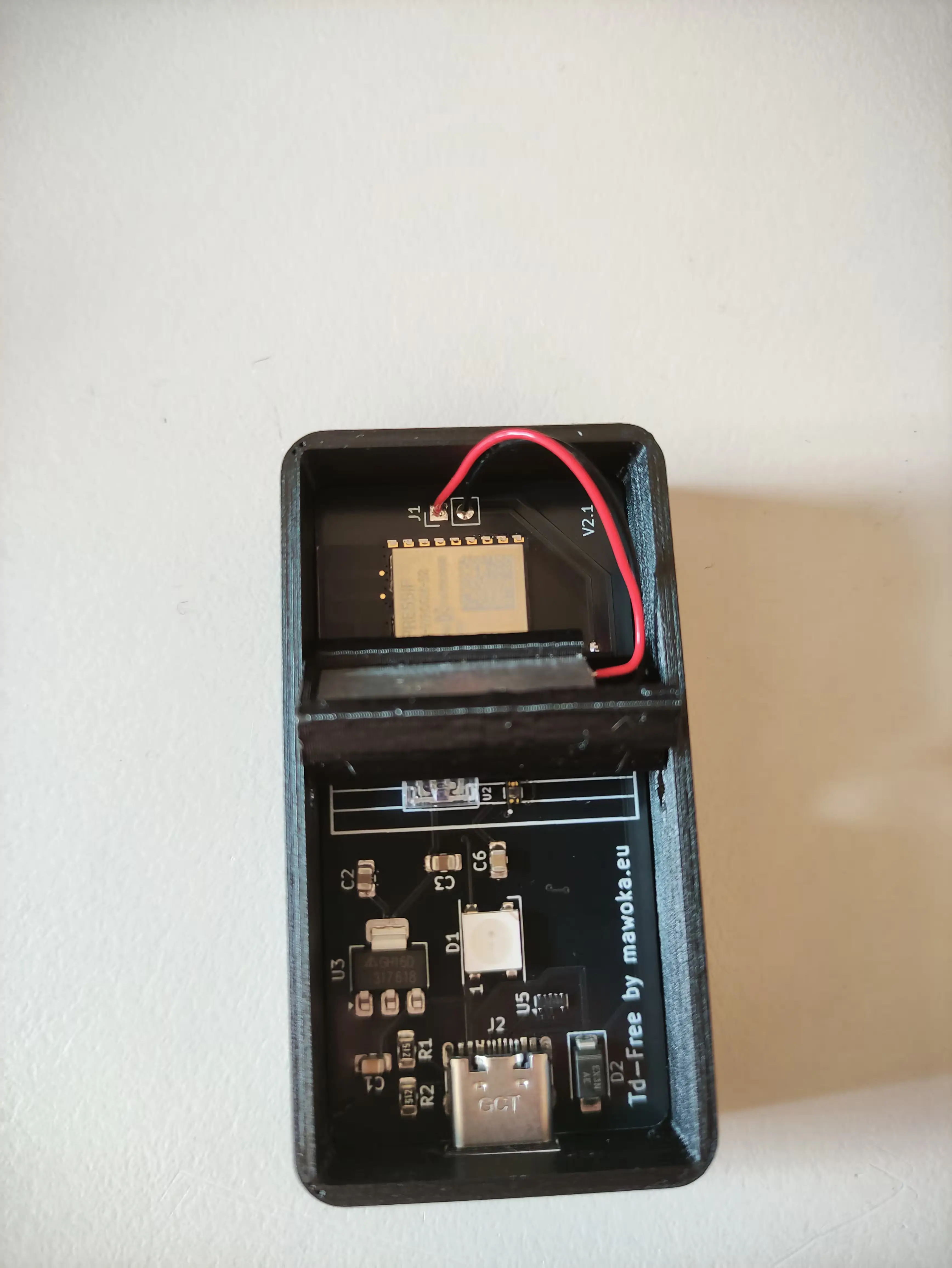
6. Put the lid on
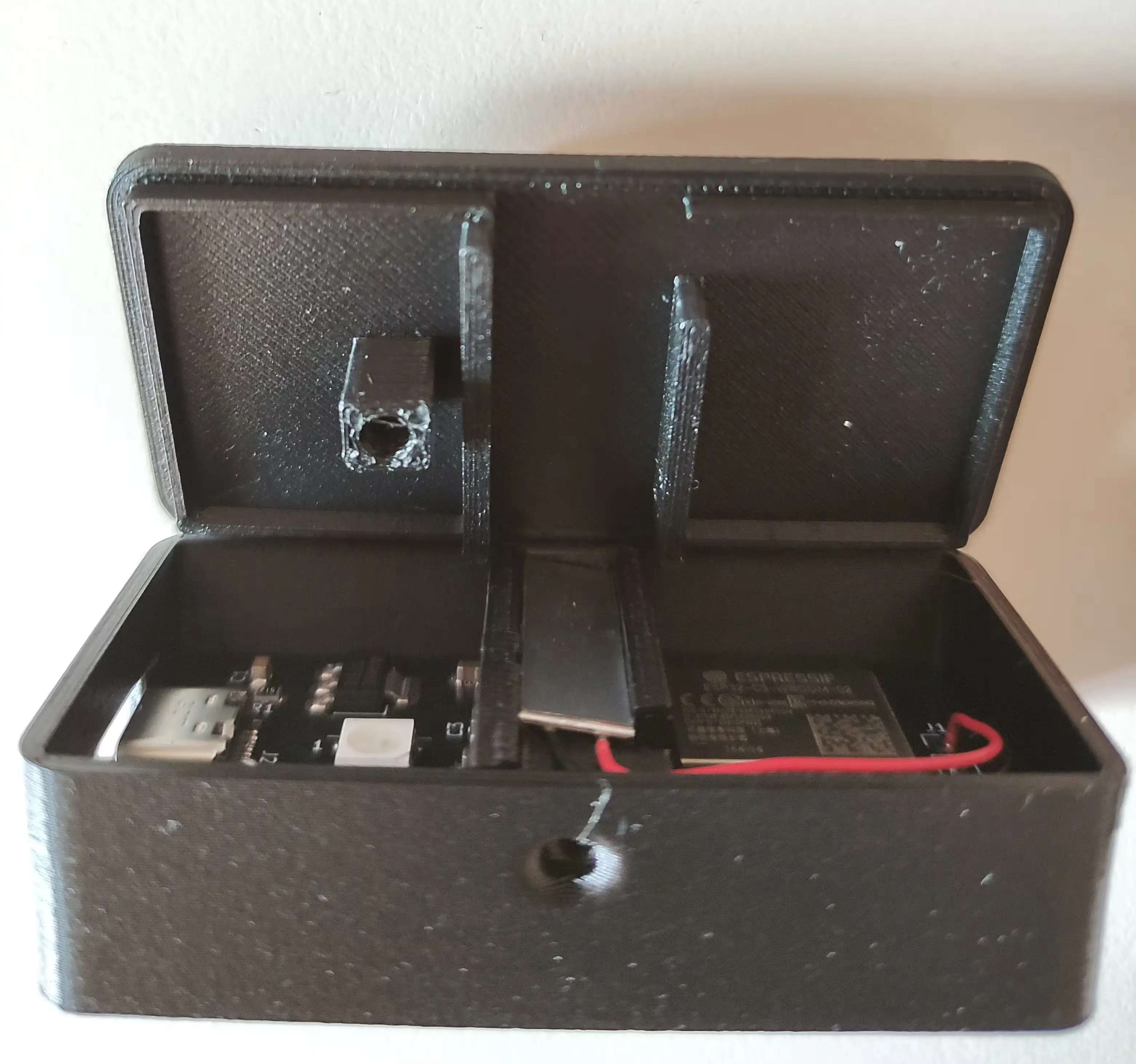
You'll have to be careful again! First, align the lid with the case and thus with the Filament Path as I've also done in the photo. Also make sure the hollow standoff is above the LED on the PCB and next to the USB-C port.
7. Close it up
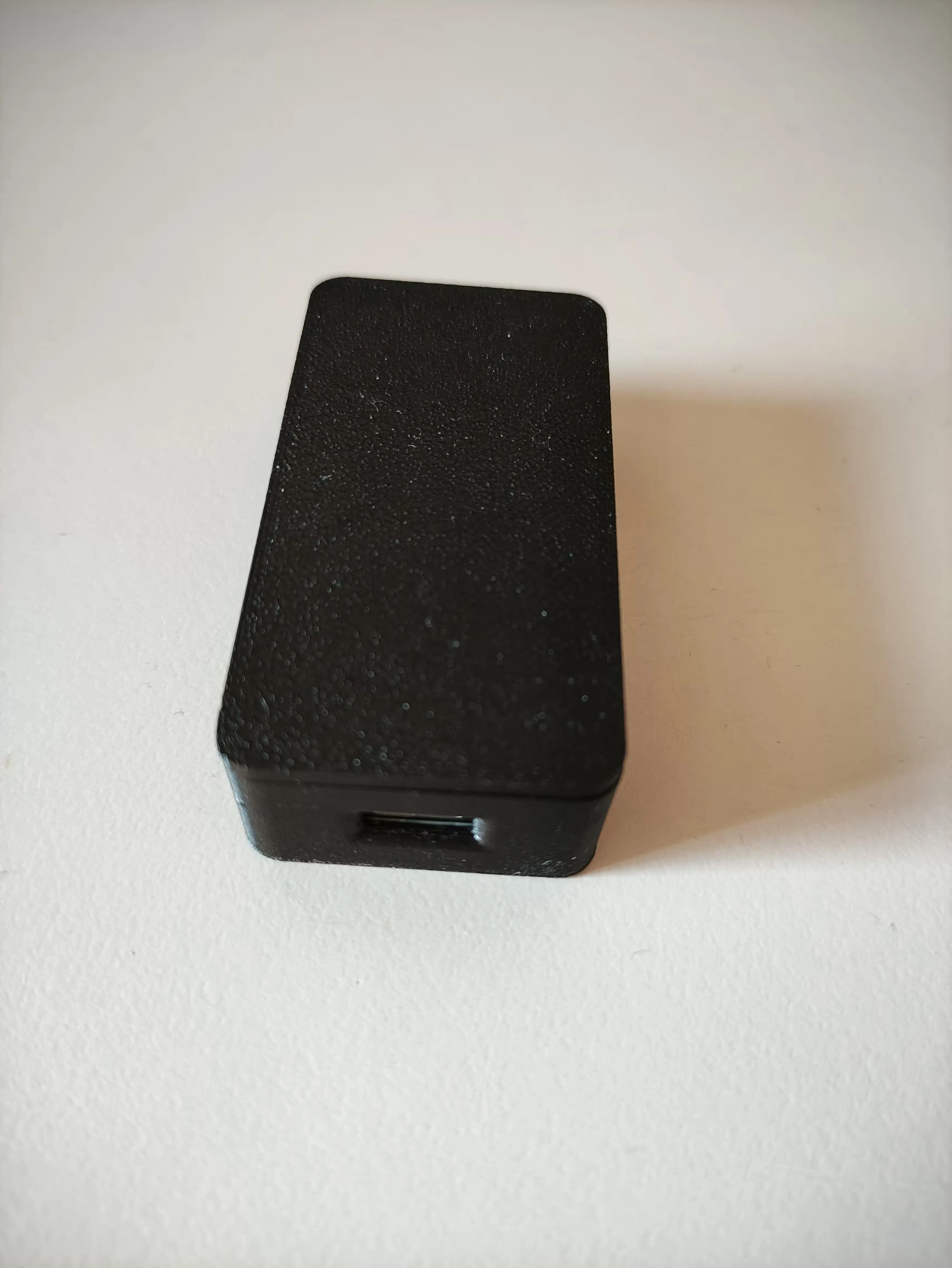
Just close the lid and you're done with the assembly. This wasn't bad at all, was it? Anyway, you've done a great job!
8. Opening it back up
This isn't part of the assembly, but it's super important to know:
Lift the lid only from the long sides, NEVER from the short sides.
Otherwise you might break a sensor off.